Fiber Optic Tapping - Tapping Setup
So let's recap, we currently know:
- How Fiber Optics Work
- How to Access a Fiber Optic Cable Mid-Span
Now let's move on to actually tapping the fiber. To begin we are going to need a few components. Note, most of these are only needed for demonstration purposes. If you were actually tapping a live fiber, the amount of hardware used would decrease. I'll make sure to note this as I explain.
The first thing we need to do is to set up a small fiber network between two computers. I am going to accomplish this with the following:
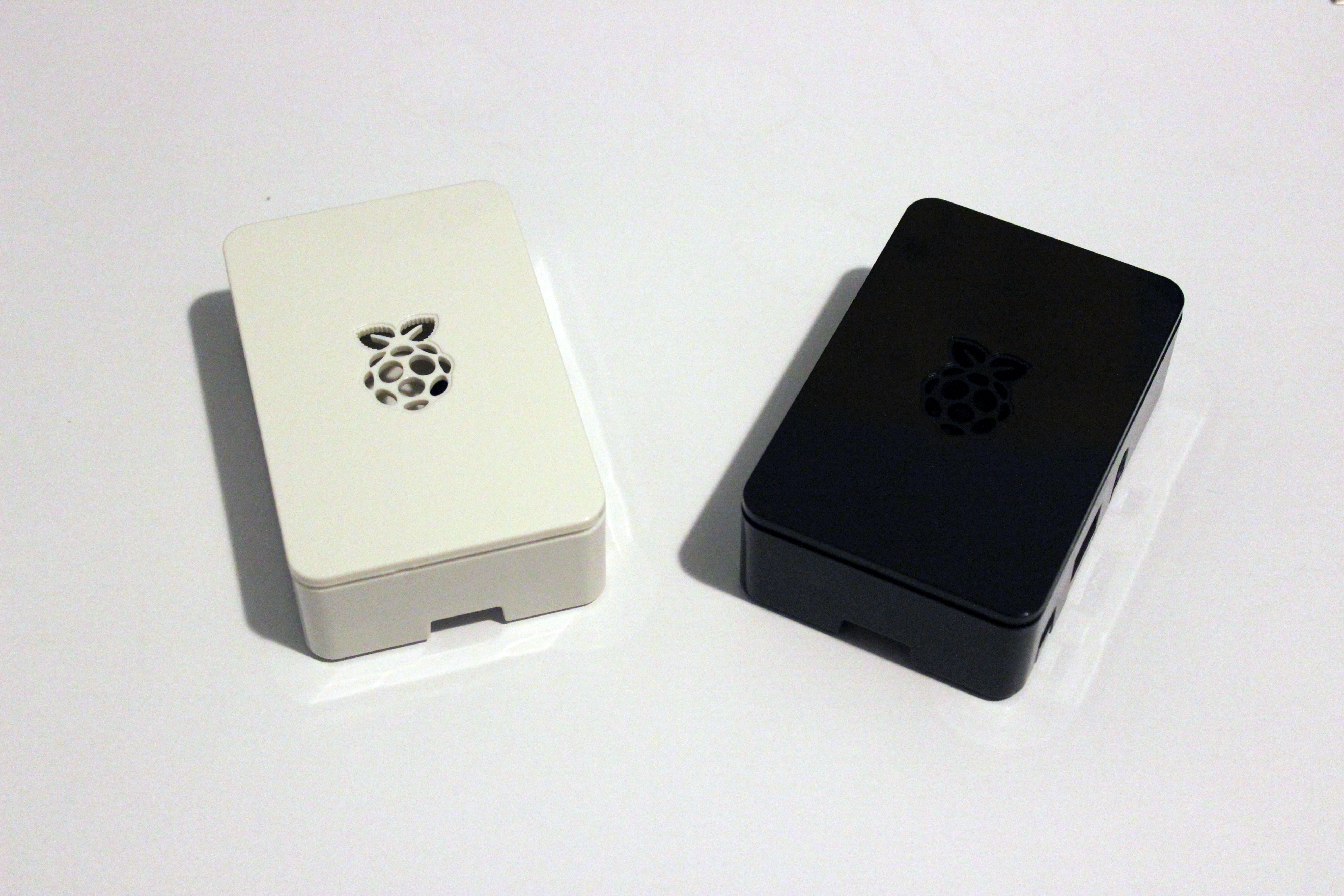
- (2) Raspberry Pi 2
- (2) Fiber Media Converter
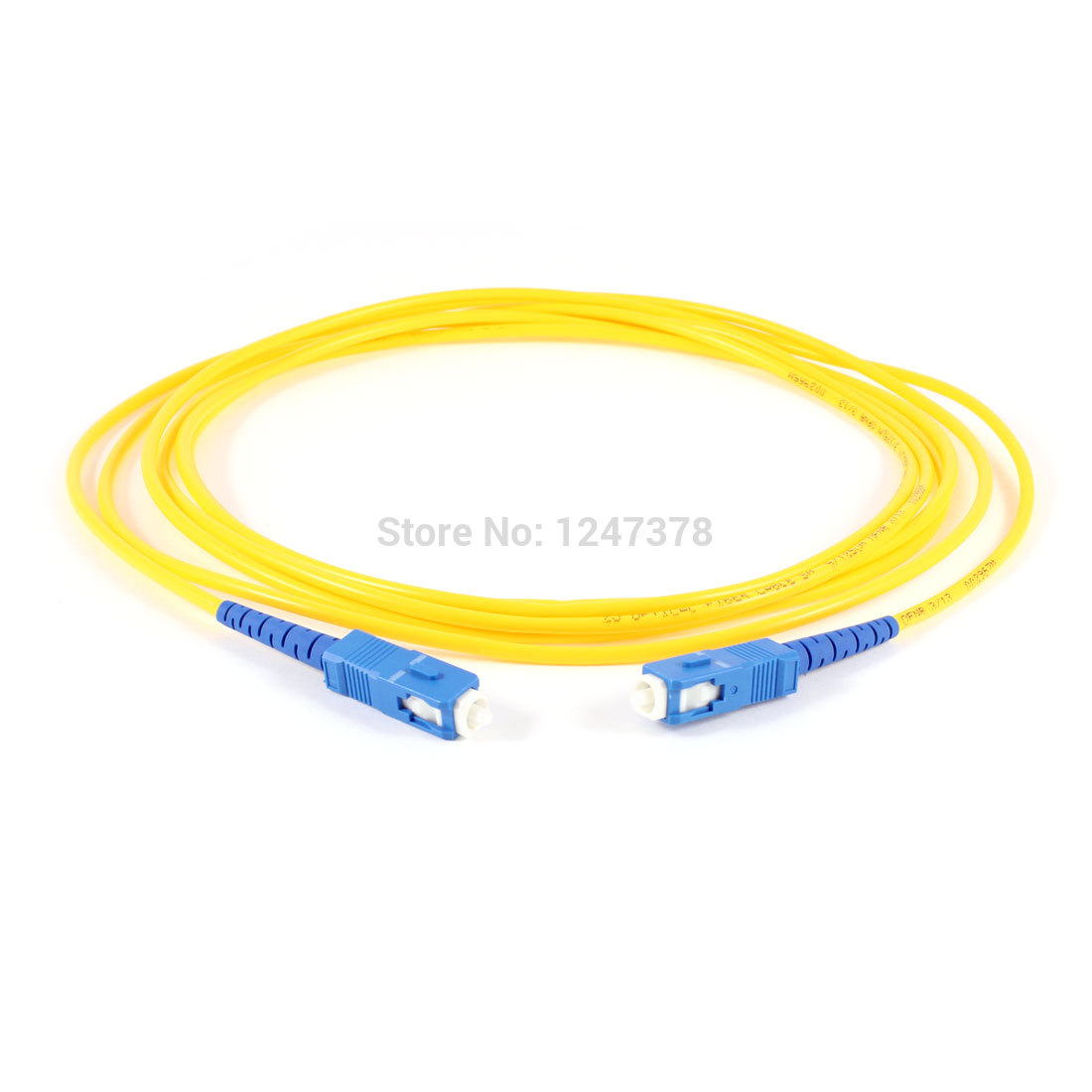
- SC->SC Duplex Multimode 62.5/125 Fiber Optic Cable
The above is only for a demonstration setup
Something I haven't covered yet is the connector types. I don't believe I need to do so because it's irrelevant to tapping since we are only concerned with the fiber behind the connector. Just keep in mind that if you're going to mimic my setup to keep the same connectors throughout, it's much easier that way.
I am going to use the two Raspberry Pi 2 machines as my computers. You could use two laptops as I did when I was doing all of my original testing and troubleshooting, I only switched to the Pi hardware as it was easier to transport to DEFCON than carrying three laptops, but I will explain both setups. For the two Pi machines, I loaded the UbuntuMate OS. I mainly chose this OS because of its performance though its interface was eye-pleasing and I wanted that for my presentation. If you're using a laptop then it doesn't really matter what OS you use, it really comes down to if your network interfaces supports Auto MDI-X as this will be a straight connection between two machines.
We now need to connect the two machines together. For this, we will use two fiber media converters (FMCs). For those that may not know, fiber media converters convert electrical signals to optical signals and vice-versa. When an electrical signal is converted to an optical signal, a wavelength, it transmits using lasers or LEDs, and receives with photodetectors. Our coupler is compatible with the 1310nm and 1550nm (nanometer) wavelengths, which is the infrared part of the light spectrum. Generally multimode operates at 1310nm and single mode operates at 1550nm.
I purchased two TP-Link MC100CM FMCs ($35 USD~) (These are no longer manufactured and have been replaced by the MC200CM. You can pick them up at Amazon). They are 10/100 compatible, multimode, SC fiber and have a range of 1.2miles. This will allow our two PIs (or laptops) to communicate with one another. This decision was based on the price and reviews. When choosing a fiber media converter you have to remember what your requirements and restrictions are:
- Wavelength
- Connector Type
- 10/100 or 10/100/1000
- Multimode or Single-mode
To elaborate; the FMC must be compatible with the coupler's wavelengths, must have the same connector types as your fiber, must be a compatible 10/100 setup or a 10/100/1000 setup, and depending on the connecting fiber, must support multimode, single-mode or both.
If you need to purchase a SC cable for your setup, you can find several at Amazon, or your local MicroCenter-like store.


I configured my setup with one Pi serving as an FTP server, and the other acting as a client. I then connected a copper cable from each Pi to each FMC, and a fiber optic cable between each FMC. Once power is applied and you give each Pi an IP, you will see the lights on the FMCs sync up and you will be able to ping each machine. This is also the same for a laptop setup.
Enter the coupler! Now that we have established a network connection between our two Pis (or laptops), we are ready to introduce the coupler into the setup.
Make sure that the fiber works first by setting up the network before you go through the trouble of accessing the internal fiber.
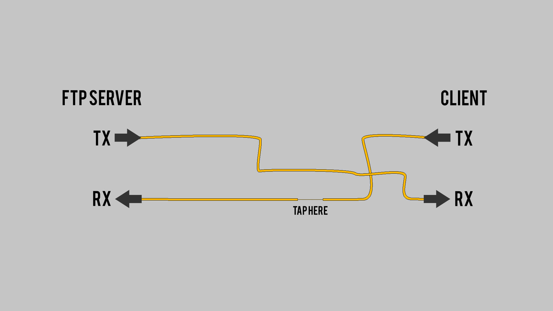
Critical note, our goal is to tap the data going from the client to the ftp server. That being the case, we need to open the fiber optic cable on the transmit side of the client FMC. If you open the wrong side of the cable, then you will be tapping the fiber line coming back from the server to the client.
Once your cable has been modified then connect it back to the FMCs and ensure the network still establishes. If so, then we can move on.
We now need to get the signal that the coupler will be tapping to a machine that can record the data. I will call this machine the "attacker's laptop". In order to get the optical signal to the attacker's laptop, we will need another FMC. This FMC is different from the ones we used earlier. This FMC needs to support single-mode, as the fiber coming out of my coupler is single-mode. It also needs to support the same wavelengths mentioned earlier, and is compatible with your other FMCs (10/100 or 10/100/1000).
I used a TP-Link MC110CS ($35 USD~) as it has the same specs as the MC100CMs, aside this one is designed to be used with single-mode cables. (Like the MC100CM, these are no longer manufactured. They have been replaced by a gigabit version called the MC210CS. You can purchase it here at Amazon)

I am using a AFL FTS-20C Fiber Optic Clip-On Coupler ($900 USD~) in my setup. If you purchased the same coupler as I did, you will likely need a "hybrid mating adapter" which can be found on Amazon as well. My coupler came with an FC end connector. However, my FMC is SC. I could've got an FMC with FC inputs on it, but I wanted continuity and opted to go with a setup that uses all the same connectors. The mating adapter's only job is to take one end connector from a fiber cable and let another, different end connector meet with it. The ends do not actually touch inside the adapter. Instead, they are "air-gapped", which is a tiny gap between the two end connectors. You suffer a little signal loss, but not enough to cause any issues. Speaking of which, you will also need a single-mode fiber optic cable. This will be used to connect the coupler to the attacker's FMC in the receive port (RX). This is then connected by a copper cable to the attacker’s laptop.

The single-mode FMC, hybrid mating adapter, single-mode cable and copper cable are needed regardless of a demonstration.
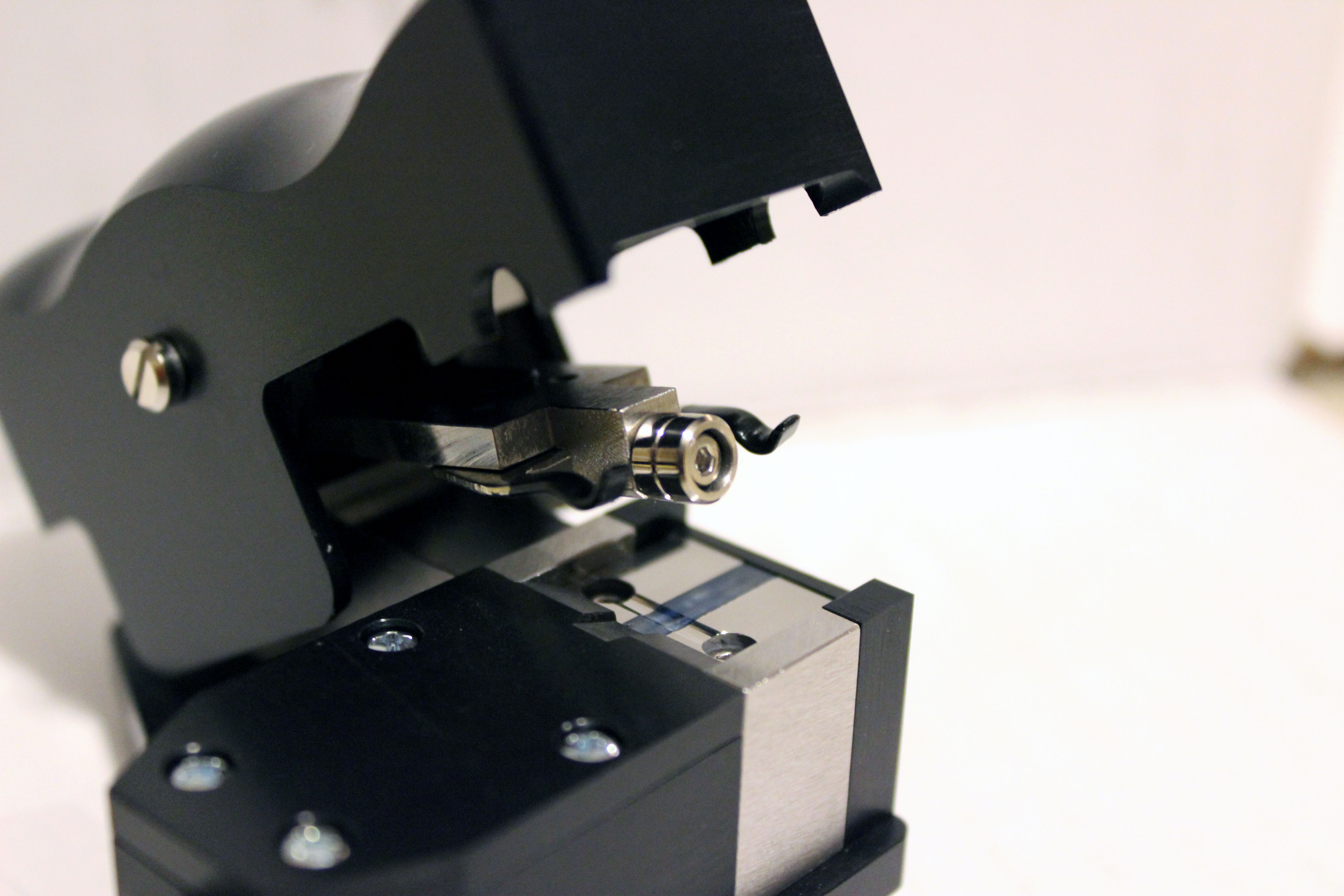
Now to place the exposed cladding into the coupler. There is a small groove in the guide wheel that provides the bend radius necessary for tapping to take place. The ultimate goal here is to place the fiber into the groove of the guide wheel and lower the coupler head down until it stops.
But take note of a few things first.
- You must remove all residual Xylene from the cladding. It may look clean and dry, but it is not. Not until you wipe it off. Any Xylene that is still present on the cladding is going to cause optical distortion and you will get not a successful tap on the fiber. However, as I mentioned in my previous post, do not get used to using paper towels. Paper towels are not soft, so wiping down the sensitive cladding with this can cause damage and will also lead to optical distortion which will stop any and all tapping. For this I used a product called Kimwipes. Kimwipes are known as delicate task wipers. This product is made specifically for cleaning microscopes, telescopes, and camera lenses; basically anything that shouldn't be scratched. You can pick up a box of 280 wipes at Amazon for such a few dollars. Grab a couple wipes and give the fiber a good cleaning (but be gentle about it).

- There are two little arms to the left and right of the guide wheel inside the coupler. The fiber cable must lay across these arms. At first, I thought my coupler was damaged because of how the arms are positioned. A call to the manufacturer later and I now know that they are positioned that way to provide the proper angle to the prism groove below the guide wheel. If the fiber cable does not lie on these two arms, you will not get any light from the tapped fiber.
- Make sure the cladding is in the groove of the guide wheel before you lower the coupler head. If you do not, and the cladding is caught anywhere else, it will instantly snap, and your cable is useless.
If you do not follow the above steps, you can and will ruin your fiber optic cable. If you break the fiber core, then that entire line of the fiber optic cable is useless and cannot be repaired
Once the fiber is properly seated in the coupler, and the coupler head is pressed down, you should notice the lights on the attacker's FMC light up in sync with the other two FMCs. At this point, you have successfully tapped into the active fiber cable. However, if you do not see any lights then, troubleshooting is going to be necessary. Conveniently, that is the topic of the next post!
This is the setup I used during my presentation at DEFCON 23.
